Picasso Configurations
There are many features in Picasso and they can be switched on/off according to the configurations. These configurations can be divided into four parts:
Global Configurations: valid for all processing tasks.
Picasso Link File: entries for Polly Configurations and Polly Defaults.
Polly Configurations: valid for single Polly or campaign.
Polly Defaults: valid for single Polly and campaign.
These three configurations are the basics for using Picasso properly.
Global Configurations
Global Configurations are mainly associated with paths, folders and figure qualities. Below is the default settings for Global Configurations:
{
"fileinfo_new": "",
"doneListFile": "",
"polly_config_folder": "",
"log_folder": "",
"gdas1_folder": "",
"defaultFile_folder": "",
"results_folder": "",
"pic_folder": "",
"pollynet_config_link_file": "",

"printLevel": 0,
"figDPI": 150,
"fontname": "DejaVu Serif",

"minDataSize": 500000,

"institute": "Ground-based Remote Sensing Group (TROPOS)",
"homepage": "http://polly.rsd.tropos.de/",
"contact": "Zhenping Yin <zhenping@tropos.de>",

"pyBinDir": "",

"flagEnableLogSubFolder": false,
"flagRenewLogFile": false,
"flagDeleteData": false,
"flagDeletePreOutputs": true,
"flagEnableCaliResultsOutput": true,
"flagEnableResultsOutput": true,
"flagEnableDataVisualization": true,
"flagDebugOutput": true,
"flagReduceMATLABToolboxDependence": false,
"flagSendNotificationEmail": false,
"flagWatermarkOn": true
}
The Global Configurations can be overridden by setting up a new .json_ file or just editing the template file in config. The details of each keyword can be found below:
Keyword |
Meaning |
Example |
|---|---|---|
fileinfo_new |
absolute path of fileinfo_new, which stores the information of polly data |
/home/zhenping/fileinfo_new.txt |
doneListFile |
absolute path of donefile_list, which stores the information of output figures |
/home/zhenping/donefile_list.txt |
polly_config_folder |
directory of polly configuration files |
/home/zhenping/pollyConfig |
log_folder |
directory of log files |
/home/zhenping/log |
gdas1_folder |
directory of GDAS1 meteorological data |
/home/zhenping/gdas1 |
defaultFile_folder |
directory of polly default files |
/home/zhenping/pollyDefaults |
results_folder |
directory for exporting processing results |
/home/zhenping/results |
pic_folder |
directory for exporting figures |
/home/zhenping/recent_plots |
pollynet_config_link_file |
absolute path of Picasso link file, which
associated polly data with polly configuration file
|
/home/zhenping/pollynet_processing_chain_link_file.xlsx |
printLevel |
% 0: log file & matlab command line;
% 1: log file only;
% 2: matlab command line only;
% 3: simple message in log file & matlab command line;
% 4: simple message in log file only;
% 5: simple message in matlab command line only;
|
0 |
figDPI |
DPI of figures |
150 |
fontname |
fontname used for figures |
DejaVu Serif |
minDataSize |
minimum data size required for data processing (Byte) |
500000 |
institute |
institute |
TROPOS |
homepage |
homepage of pollynet |
|
contact |
contact |
zhenping <zhenping@tropos.de> |
pyBin |
path of python.exe |
/home/zhenping/anaconda3/bin |
flagDeleteData |
whether to delete polly data after being processed. |
true |
flagDeletePreOutputs |
whether to delete previous results for the same polly data. |
true |
flagEnableDataVisualization |
whether to activate data visualization |
true |
flagWatermarkOn |
whether to attach water-mark on each figure |
true |
flagEnableCaliResultsOutput |
whether to enable calibration results output |
true |
flagEnableResultsOutput |
whether to enable results output |
true |
Picasso Link File
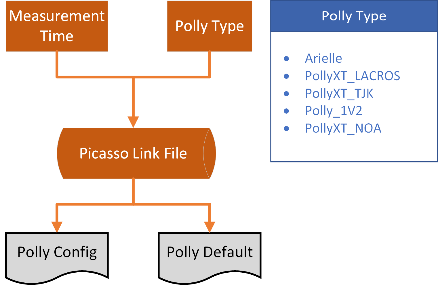
Picasso Link File.
Picasso Link File is the logbook for different campaigns and can be used to search Polly Configurations and Polly Defaults for different polly data. Picasso Link File contains basic information about campaigns and assigns Polly Configuration file and Polly Defaults file. If a new campaign was ready, the relevant information of this campaign should be added into Picasso Link File in case the campaign data can be processed.
Note
If no entry for the polly data can be found, Picasso will jump over the current data.
Polly Configurations
Polly Configurations can be specified for each polly data. They control how data was pre-processed, the thresholds of retrievals and aerosol/cloud classifications, boundaries for data visualization, etc. The Polly Configurations can be overridden by setting up a new .json_ file. The details of each keyword can be found below:
Keyword |
Meaning |
Example |
Reference |
|---|---|---|---|
flagCorrectFalseMShots |
whether to correct the invalid shots stored in the netcdf files.
(I don’t know the reason yet, but it does exist in pollyxt_tropos
for a period of time)
|
true |
— |
flagFilterFalseMShots |
whether to filter out the profiles with invalid shots. (Since I
don’t know whether it’s trustable for these profiles, I will
leave this keyword for future development.)
|
false |
— |
flagForceMeasTime |
whether to fix measurement time according to the mshots instead
of using the original PC time
|
false |
— |
flagDTCor |
whether to implement deadtime correction |
true |
— |
flagWVCalibration |
whether to implement water vapor calibration |
true |
— |
flagLCCalibration |
whether to enable lidar calibration |
true |
— |
flagDepolCali |
whether to enable lidar depolarization calibration |
true |
— |
flagUsePreviousDepolCali |
whether to take previous lidar depolarization calibration results
when no calibration is available
|
true |
— |
flagUsePreviousWVconst |
whether to take previous lidar water vapor calibration results when
no water vapor calibration is available
|
true |
— |
flagUsePreviousLC |
whether to take previous lidar calibration constants when no lidar
calibration is available
|
true |
— |
flagUseSameRefH |
whether to take the same reference height for aerosol retrievals at all
available wavelength
|
false |
— |
flagSigTempCor |
whether to implement signal temperature correction |
false |
— |
tempCorFunc |
temperature correction function for each channel |
[“1”, “exp(-0.001*T)”, “1”] (Unit: Kelvin)
|
— |
flagAutoscaleRCS |
to control whether to configure the color-range for range corrected
signal in an automatic way
|
true |
— |
flagMolDepolCali |
to control whether to use molecular depolarization calibration |
false |
H. Baars, PhD thesis, 2012
|
MWRFolder |
The folder of prw results from MWR. (This is only for LACROS) |
C:\Users\zhenping\Desktop\Picasso\test\
read_IWV_from_MWR
|
— |
dataFileFormat |
regular expression to extract the data and time info from polly data file.
(This is based on the syntax of matlab regexp)
|
(?<year>\d{4})_(?<month>\d{2})
_(?<day>\d{2})_\w*_(?<hour>\d{2})
_(?<minute>\d{2})_(?<second>\d{2})\w*.nc
|
— |
gdas1Site |
gdas1 site for the current campaign. |
warsaw |
— |
max_height_bin |
the number of bins you want to extract for each profile. (Normally,
the high altitude bins only contain noise. If you load too much bins, you
will slow down the whole processing process)
|
2500 |
— |
first_range_gate_indx |
the first bin for each channel. (It’s highly suggested to
tune this parameter to compensate the lag among different channels)
|
[261, 261, 261, 261, 261,
261, 261, 261, 262, 262, 262, 262]
|
— |
first_range_gate_height |
The height for the first range bin. [m]. You need to
take great care for this parameter, since it will create large bias for extinction
coefficient with Raman method. Look for advice from hardware scientist if you
are not certain about this. 78.75 m
->(The unit is only for demonstration, don’t set it in the config files)
|
— |
|
dtCorMode |
deadtime correction mode.
1: use the parameters saved in the netcdf files
2: nonparalyzable correction with user define deadtime
3: paralyzable correction with user defined parameters
4: no deadtime correction
|
1 |
— |
dt |
parameters for deadtime correction. If “dtCorMode” is set to be ‘2’, only the
deadtime for each channel need to be set here with unit of ns.
If “dtCorMode” is set to be ‘3’, the correction parameters
need to be set accordingly. You can take [pollyxt_tropos_config.json]
(/config/pollyxt_tropos_config.json) as an example
|
[[0.0, 0.972992, 0.00353332, -7.90981e-006,
1.06451e-007, 1.42895e-009],
[0, 1.0117, -0.0014, 0.0002, -0.0000, 0.0000],
[0, 0.9674, 0.0023, 0.0000, 0.0000, 0.0000],
[0, 0.9929, 0.0000, 0.0001, -0.0000, 0.0000],
[0, 0.9843, 0.0022, 0.0001, -0.0000, 0.0000],
[0, 0.9391, 0.0063, -0.0001, 0.0000, -0.0000],
[0, 1.0035, 0.0003, 0.0001, -0.0000, 0.0000],
[0, 1.0000, 0, 0, 0, 0],
[0, 1.0000, 0.0029, 0.0000, 0.0000, 0.0000],
[0, 1.0000, 0.0028, 0.0000, 0.0000, 0.0000],
[0, 1.0000, 0.0028, 0.0000, 0.0000, 0.0000],
[0, 1.0000, 0.0025, 0.0000, 0.0000, 0.0000],
[0, 1, 0, 0, 0, 0]]
|
— |
bgCorRangeIndx |
the bottom and top index of signal to calculate the background |
[10, 240]
|
— |
mask_SNRmin |
the SNR threshold to mask noisy bins |
[1.6, 1, 1, 1, 1.5, 1, 1, 1.5, 1, 1, 1, 1, 1]
|
— |
depol_cali_mode |
depolarization calibration mode:
1: automatic searching based on depolarization calibration angle
2: fixed calibration time according to input
|
1 |
— |
depol_cal_time_fixed_p_start |
fixed timestamp for the start of depolarization calibration period at positive angle. |
[“05:30:00”] for the start time of
depolarization calibration at 05:30:00 each day,
or [“20130101 05:30:00”] for depolarization
calibration at 2013-01-01 05:30:00
|
— |
depol_cal_time_fixed_p_end |
fixed timestamp for the stop of depolarization calibration period at positive angle. |
[“05:35:30”]
|
— |
depol_cal_time_fixed_m_start |
fixed timestamp for the start depolarization calibration period at negative angle. |
[“05:35:30”]
|
— |
depol_cal_time_fixed_m_end |
fixed timestamp for the stop of depolarization calibration period at negative angle. |
[“05:40:00”]
|
— |
init_depAng |
the initial angle of the polariser withou depo calibration [degree] |
0 |
— |
maskDepCalAng |
the mask for postive and negative calibration angle.
‘none’ means invalid profiles with different depol_cal_angle
|
[“none”, “none”, “p”, “p”,
“p”, “p”, “p”, “p”, “p”,
“p”, “none”, “none”, “n”,
“n”, “n”, “n”, “n”, “n”,
“n”, “n”]
|
— |
depol_cal_minbin_{wavelength} |
the minimum bin used for depolarization calibration |
40 |
— |
depol_cal_maxbin_{wavelength} |
the maximum bin used for depolarization calibration |
300 |
— |
depol_cal_SNRmin_{wavelength} |
Threshold for the minimum SNR used in depol-calibration.
There are four signal profiles used in the calibration, total channel at 45
and cross channel at 45. Therefore, an array of four element need to be
configured. Namely, [total+45, total?45, cross+45, cross?45]
|
[1, 1, 1, 1]
|
— |
depol_cal_sigMax_{wavelength} |
The maximum signal strength could be used for
depol-calibration to prevent signal pileup effects
[1500, 1500, 1500, 1500] (photon count)
|
— |
|
rel_std_dplus_{wavelength} |
Threshold for maximum relative uncertainty of signal ratio
at +45 depol-calibration. If relative uncertainty exceed this value,
it states there could be clouds or too weak signal for this
calibration period.
|
0.2 |
— |
rel_std_dminus_{wavelength} |
Threshold for maximum relative uncertainty of signal ratio
at -45 depol-calibration.
|
0.2 |
— |
depol_cal_segmentLen_{wavelength} |
The small region for evaluating the uncertainty of depol calibration |
40 |
— |
depol_cal_smoothWin_{wavelength} |
The smoothing window for depol-calibration |
8 |
— |
isFR |
flag of far-range channel |
[1, 1, 1, 1, 1, 1, 1, 1, 0, 0, 0, 0, 0]
|
— |
isNR |
flag of near-range channel |
[0, 0, 0, 0, 0, 0, 0, 0, 1, 1, 1, 1, 0]
|
— |
is532nm |
flag of 532nm channel |
[0, 0, 0, 0, 1, 1, 0, 0, 1, 0, 0, 0, 0]
|
— |
is355nm |
flag of 355nm channel |
[1, 1, 0, 0, 0, 0, 0, 0, 0, 0, 1, 0, 0]
|
— |
is1064nm |
flag of 1064nm channel |
[0, 0, 0, 0, 0, 0, 0, 1, 0, 0, 0, 0, 0]
|
— |
isTot |
flag of total channel |
[1, 0, 0, 0, 1, 0, 0, 1, 1, 0, 1, 0, 0]
|
— |
isCross |
flag of cross polarized channel |
[0, 1, 0, 0, 0, 1, 0, 0, 0, 0, 0, 0, 0]
|
— |
is387nm |
flag of 387nm channel |
[0, 0, 1, 0, 0, 0, 0, 0, 0, 0, 0, 1, 0]
|
— |
is407nm |
flag of 407nm channel |
[0, 0, 0, 1, 0, 0, 0, 0, 0, 0, 0, 0, 0]
|
— |
is607nm |
flag of 607nm channel |
[0, 0, 0, 0, 0, 0, 1, 0, 0, 1, 0, 0, 0]
|
— |
channelTag |
label of each channel |
[“FR-total-355 nm”, “FR-cross-355 nm”,
“FR-387 nm”, “FR-407 nm”,
“FR-total-532 nm”, “FR-cross-532 nm”,
“FR-607 nm”, “FR-total-1064 nm”,
“NR-total-532 nm”, “NR-607 nm”,
“NR-total-355 nm”, “NR-387 nm”,
“unknown”]
|
— |
minPC_fog |
The minimum photon count for non-fog profile. The detected photon
count between 40th and 120th bin (above the first bin) for each 30s profile
will be accumulated for the fog profile screening.
|
60 |
Baars H. et al, AMT, A1, 2016
|
TR |
Transmission ratio for different channel. |
[0.898, 1086, 1, 1, 1.45, 778.8, 1, 1, 1, 1, 1, 1, 1]
|
Engelmann, R., Kanitz, T., Baars, H., Heese, B.,
Althausen, D., Skupin, A., Wandinger, U.,
Komppula, M., Stachlewska, I. S., Amiridis, V.,
Marinou, E., Mattis, I., Linne, H., and Ansmann, A.:
The automated multiwavelength Raman polarization
and water-vapor lidar PollyXT: the neXT generation,
Atmos. Meas. Tech., 9, 1767-1784,
10.5194/amt-9-1767-2016, 2016.
|
overlapCalMode |
1:estimate the overlap function based on the near-range signal.
2: calculate the overlap function with Raman method
(U. Wandinger, et al, Applied Optics, 2002)
|
1 |
Wandinger, U. and Ansmann, A.: Experimental determination
of the lidar overlap profile with Raman lidar, Appl. Opt., 41, 511-514, 2002.
|
overlapCorMode |
0: no overlap correction
1:overlap correction with using the default overlap function
2: overlap correction with using the calculated overlap function
3: overlap correction with gluing near-range and far-range signal
|
1 |
— |
overlapSmoothBins |
vertical window (bins) for smoothing the noisy overlap function |
8 |
— |
saturate_thresh |
the threshold for signal saturation (MHz) |
100 |
— |
heightFullOverlap |
height for the base of full overlap |
[500, 500, 500, 500, 500, 500, 500,
500, 150, 150, 150, 150, 150]
|
— |
minSNR_4_sigNorm |
The minimum SNR requirement for the signal used for signal
normalization both for near- and far- range signal.
|
10 |
— |
cloudScreenMode |
1: using signal gradient; 2: using Zhao’s algorithm |
1 |
Zhao, C., Wang, Y., Wang, Q., Li, Z., Wang, Z.,
and Liu, D.: A new cloud and aerosol layer
detection method based on micropulse lidar
measurements, Journal of Geophysical Research:
Atmospheres, 119, 6788-6802, 10.1002/2014JD021760, 2014.
|
maxSigSlope4FilterCloud |
The slope threshold for cloud screening. The screening is based
on the slope of the Range Corrected Signal(photon count * m^2).
In theory, this should be done with the attenuated backscatter.
Since the lidar constant is unknown and cloud-screen is highly
important for retrieving aerosol profiles, this is the only
applicable way to my knowledge. Attention should be paid for
the threshold setting, because it’s dependent on the the order
of ND filter. But it’s not very sensitive because cloud
scattering signal is much more stronger than that from
aerosols. You can keep this value if there is no dramatic
changes of ND filter(more than 1)
|
3e6 |
— |
maxSigSlope4FilterCloud_NR |
The slope threshold for cloud screening with using NR signal |
0.5e6 |
— |
intNProfiles |
Accumulated profiles for retrieving. |
120 |
— |
minIntNProfiles |
minimum integral profiles for aerosol retrieving |
90 |
— |
meteorDataSource |
the data source for meteorological data. If the current data does
not exist. It will turn to standard atmosphere model.
|
gdas1 |
— |
radiosondeSitenum |
The site number for the nearest radiosonde launching site. |
14430 |
— |
minDecomLogDist{wavelength} |
0.2 |
— |
|
maxDecomHeight{wavelength} |
8000 |
— |
|
maxDecomThickness{wavelength} |
700 |
— |
|
decomSmoothWin{wavelength} |
The smoothing window for molecular corrected signal
used in Douglas-Peucker decomposition algorithm.
|
20 |
— |
minRefThickness{wavelength} |
The minimum thickness for the reference height.
There is thickness test in the RayleighFit function which
will ensure the minimum thickness of the reference height
|
500 m |
— |
minRefDeltaExt{wavelength} |
The maximum slope difference between measured signal
and molecule signal. This threshold is used in RayleighFit
slope test which will examine whether
$slope_{molecular signal}in[slope_{measured signal}
- ksigma_{slope_{measured signal}}, slope_{measured
signal} + ksigma_{slope_{measured signal}}]$
|
2 |
— |
minRefSNR{wavelength} |
The minimum SNR for the accumulated signal at the tested
reference height.
|
5 |
— |
LR{wavelength} |
Default lidar ratio for Klett retrieving method |
50 sr |
— |
refBeta{wavelength} |
Reference value for Klett and Raman method |
2e-8 |
— |
smoothWin_klett_{wavelength} |
smoothing window for klett method |
21 |
— |
maxIterConstrainFernald |
The maximum iterations for searching the best Lidar Ratio with
Constrained-AOD fernald method
|
20 sr |
— |
minLRConstrainFernald |
The minimum lidar ratio used for Constrained-AOD fernald method |
1 sr |
— |
maxLRConstrainFernald |
The maximum lidar ratio used for Constrained-AOD fernald method |
150 sr |
— |
minDeltaAOD |
The minimum AOD deviation that is required for Constrained-AOD
fernald method
|
0.01 |
— |
minRamanRefSNR387 |
The minimum SNR for the signal at the reference height.
If SNR at the reference height is smaller than this value,
raman method will not implemented.
|
40 |
— |
minRamanRefSNR607 |
The minimum SNR for the signal at the reference height.
If SNR at the reference height is smaller than this value,
raman method will not implemented.
|
20 |
— |
angstrexp |
Default angstroem exponent for Raman method |
0.9 |
— |
smoothWin_raman_{wavelength} |
smoothing window for raman method |
61 |
— |
LCMeanWindow |
The window for calculating the Lidar Constant |
50 |
— |
LCMeanMinIndx |
The minimum bin used for lidar constant calculation |
70 |
— |
LCMeanMaxIndx |
The maximum bin used for lidar constant calculation |
1000 |
— |
LCCalibrationStatus |
The tag for lidar calibration status, which will displayed
in the output figures
|
[“none”, “Klett”, “Raman”, “Defaults”, “History”]
|
— |
quasi_smooth_h |
temporal smoothing window for quasi retrieving method.
For consistency, this parameter should be set for each channel
|
[1, 1, 1, 1, 1, 1, 1, 1, 1, 1, 1, 1, 1]
|
— |
quasi_smooth_t |
spatial smoothing window for quasi retrieving method.
For consistency, this parameter should be set for each channel
|
[1, 1, 1, 1, 1, 1, 1, 1, 1, 1, 1, 1, 1]
|
— |
IWV_instrument |
the data source of IWV. (‘mwr’ or ‘aeronet’) |
AERONET |
— |
maxIWVTLag |
The minumum lag required for water vapor calibration between
IWV data and lidar water vapor measurement.
|
0.1666 |
— |
tTwilight |
span of the twilight |
0.0347 |
— |
hWVCaliBase |
The minimum height used for calculating the IWV from lidar measurement. |
120 |
— |
minHWVCaliTop |
The minimum top height required for calculating the IWV from lidar measurement. |
2000 |
— |
clear_thres_par_beta_1064 |
The threshold for discriminating clear atmosphere based on particle
backscatter at 1064nm
|
1e-8 m^{-1} |
Baars, H., Seifert, P., Engelmann, R.,
and Wandinger, U.: Target categorization of
aerosol and clouds by continuous
multiwavelength-polarization lidar measurements,
Atmospheric Measurement Techniques,
10, 3175-3201, 10.5194/amt-10-3175-2017, 2017.
|
turbid_thres_par_beta_1064 |
The threshold for discriminating turbid atmosphere based on
particle backscatter at 1064nm
|
2e-7 m^{-1} |
Baars, H., Seifert, P., Engelmann, R.,
and Wandinger, U.: Target categorization of
aerosol and clouds by continuous
multiwavelength-polarization lidar measurements,
Atmospheric Measurement Techniques,
10, 3175-3201, 10.5194/amt-10-3175-2017, 2017.
|
turbid_thres_par_beta_532 |
The threshold for discriminating turbid atmosphere based on particle
backscatter at 532nm
|
2e-7 m^{-1} |
— |
droplet_thres_par_depol |
The threshold for discriminating cloud droplets based on particle
depolarization ratio at 532nm
|
0.05 |
— |
spheroid_thres_par_depol |
The threshold for discriminating spheriod paricles based on particle
depolarization ratio at 532nm
|
0.07 |
Baars, H., Seifert, P., Engelmann, R.,
and Wandinger, U.: Target categorization of
aerosol and clouds by continuous
multiwavelength-polarization lidar measurements,
Atmospheric Measurement Techniques,
10, 3175-3201, 10.5194/amt-10-3175-2017, 2017.
|
unspheroid_thres_par_depol |
The threshold for discriminating unspheriod paricles based on particle
depolarization ratio at 532nm
|
0.2 |
Baars, H., Seifert, P., Engelmann, R.,
and Wandinger, U.: Target categorization of
aerosol and clouds by continuous
multiwavelength-polarization lidar measurements,
Atmospheric Measurement Techniques,
10, 3175-3201, 10.5194/amt-10-3175-2017, 2017.
|
ice_thres_par_depol |
The threshold for discriminating ice crystals based on particle
depolarization ratio at 532nm
|
0.35 |
Baars, H., Seifert, P., Engelmann, R.,
and Wandinger, U.: Target categorization of
aerosol and clouds by continuous
multiwavelength-polarization lidar measurements,
Atmospheric Measurement Techniques,
10, 3175-3201, 10.5194/amt-10-3175-2017, 2017.
|
ice_thres_vol_depol |
The threshold for discriminating ice crystals based on volume
depolarization ratio at 532nm
|
0.3 |
Baars, H., Seifert, P., Engelmann, R.,
and Wandinger, U.: Target categorization of
aerosol and clouds by continuous
multiwavelength-polarization lidar measurements,
Atmospheric Measurement Techniques,
10, 3175-3201, 10.5194/amt-10-3175-2017, 2017.
|
large_thres_ang |
The threshold for discriminating large particles based on angstroem exponent |
0.75 |
Baars, H., Seifert, P., Engelmann, R.,
and Wandinger, U.: Target categorization of
aerosol and clouds by continuous
multiwavelength-polarization lidar measurements,
Atmospheric Measurement Techniques,
10, 3175-3201, 10.5194/amt-10-3175-2017, 2017.
|
small_thres_ang |
The threshold for discriminating small particles based on angstroem exponent |
0.5 |
Baars, H., Seifert, P., Engelmann, R.,
and Wandinger, U.: Target categorization of
aerosol and clouds by continuous
multiwavelength-polarization lidar measurements,
Atmospheric Measurement Techniques,
10, 3175-3201, 10.5194/amt-10-3175-2017, 2017.
|
cloud_thres_par_beta_1064 |
The threshold for discriminating cloud layers based on quasi particle
backscatter at 1064nm
|
2e-5 m^{-1} |
Baars, H., Seifert, P., Engelmann, R.,
and Wandinger, U.: Target categorization of
aerosol and clouds by continuous
multiwavelength-polarization lidar measurements,
Atmospheric Measurement Techniques,
10, 3175-3201, 10.5194/amt-10-3175-2017, 2017.
|
min_atten_par_beta_1064 |
The minimum attenuation factor could be expected at the first 250m
penatration depth
|
10 |
Baars, H., Seifert, P., Engelmann, R.,
and Wandinger, U.: Target categorization of
aerosol and clouds by continuous
multiwavelength-polarization lidar measurements,
Atmospheric Measurement Techniques,
10, 3175-3201, 10.5194/amt-10-3175-2017, 2017.
|
search_cloud_above |
The parameter is used in cloud top detection. The cloud top will be searched
between the first bin with quasi particle backscatter at 1064nm larger than
cloud_thres_par_beta_1064 and +search_height_above
|
300 m |
Baars, H., Seifert, P., Engelmann, R.,
and Wandinger, U.: Target categorization of
aerosol and clouds by continuous
multiwavelength-polarization lidar measurements,
Atmospheric Measurement Techniques,
10, 3175-3201, 10.5194/amt-10-3175-2017, 2017.
|
search_cloud_below |
The parameter is used in cloud base detection. The cloud base will be searched
between the first bin with quasi particle backscatter at 1064nm larger than
cloud_thres_par_beta_1064 and -search_height_below
|
100 m |
Baars, H., Seifert, P., Engelmann, R.,
and Wandinger, U.: Target categorization of
aerosol and clouds by continuous
multiwavelength-polarization lidar measurements,
Atmospheric Measurement Techniques,
10, 3175-3201, 10.5194/amt-10-3175-2017, 2017.
|
overlap{wavelength}Color |
the color settings for the line of overlap |
[0, 255, 64]
|
— |
xLim_Profi_Bsc |
x-range of the profile of aerosol backscatter |
[-0.1, 10] Mm^{-1}sr^{-1}
|
— |
xLim_Profi_NR_Bsc |
x-range of the profile of aerosol backscatter retrieved with near-range signal |
[-0.1, 10] Mm^{-1}sr^{-1}
|
— |
xLim_Profi_Ext |
x-range of the profile of aerosol extinction coefficient |
[-1, 300] Mm^{-1}
|
— |
xLim_Profi_NR_Ext |
x-range of the profile of aerosol extinction coefficient retrieved
with near-range signal
|
[-1, 300] Mm^{-1}
|
— |
xLim_Profi_WV_RH |
x-range (z-range) of the profile (time-height plot) of water vapor mixing ratio |
[0, 10] g*kg^{-1}
|
— |
xLim_Profi_RCS |
x-range of the profile of range corrected signal |
[0.3, 10] (*1e6 a.u.)
|
— |
xLim_Profi_LR |
x-range of the profile of lidar ratio |
[0, 120] sr
|
— |
yLim_LC_{wavelength} |
y-range of the profile of lidar constant at certain wavelength |
[0, 1e14]
|
— |
yLim_LC_ratio_{wavelength1}_{wavelength2} |
y-range of the scatter plot of the lidar constant ratio at two given wavelength |
[0, 1]
|
— |
yLim_WVConst |
y-range of the profile of water vapor calibration constant |
[0, 20]
|
— |
yLim_FR_RCS |
y-range of the profile of range corrected signal
(time-height plot of signal saturation bits)
from far-range channels
|
[0, 20000] m
|
— |
yLim_NR_RCS |
y-range of the profile of range corrected signal
(time-height plot of signal saturation bits)
from near-range channels
|
[0, 3000] m
|
— |
yLim_att_beta |
y-range of the time-height plot of far-field attenuated backscatter |
[0, 15000] [m]
|
— |
yLim_att_beta_NR |
y-range of the time-height plot of near-field attenuated backscatter |
[0, 3000] [m]
|
— |
yLim_Quasi_Params |
y-range of aerosol optical products retrieved by quasi-retrieving method |
[0, 12000] m
|
— |
yLim_WV_RH |
y-range of the profile of water vapor mixing ratio (relative humidity) |
[0, 7000] m
|
— |
yLim_Profi_Ext |
y-range of the profile of extinction coefficient |
[0, 5000] m
|
— |
yLim_Profi_LR |
y-range of the profile of lidar ratio |
[0, 5000] m
|
— |
yLim_Profi_DR |
y-range of the profile of volume/particle depolarization ratio |
[0, 20000] m
|
— |
yLim_Profi_Bsc |
y-range of the profile of aerosol backscatter |
[0, 20000] m
|
— |
yLim_Profi_WV_RH |
y-range of the profile of water vapor mixing ratio (relative humidity) |
[0, 7000] m
|
— |
yLim_depolConst_{wavelength} |
y-range of the profile of depolarization calibration constant at certain wavelength |
[0, 0.2]
|
— |
zLim_att_beta_{wavelength} |
z-range of the time-height plot of attenuated backscatter |
[0, 15] Mm^{-1}sr^{-1}
|
— |
zLim_quasi_beta_{wavelength} |
z-range of the time-height plot of quasi aerosol backscatter coefficient |
[0, 8] Mm^{-1}sr^{-1}
|
— |
zLim_quasi_Par_DR_532 |
z-range of the time-height plot of quasi particle depolarization ratio |
[0, 0.4]
|
— |
zLim_FR_RCS_{wavelength} |
z-range of the time-height plot of range corrected signal from far-range channels |
[1e-2, 30] (1e6 a.u.)
|
— |
zLim_NR_RCS_{wavelength} |
z-range of the time-height plot of range corrected signal from near-range channels |
[1e-2, 5] (1e6 a.u.)
|
— |
zLim_VolDepol_{wavelength} |
z-range of volume depolarization ratio |
[0, 0.3]
|
— |
colormap_basic |
basic colormap (chiljet, eleni, CALIPSO, labview):
1. range corrected signal
2. volume depolarization ratio
3. attenuated backscatter
4. quasi particle backscatter
5. quasi angstroem exponent
6. quasi particle depolarization ratio
|
chiljet |
— |
PI |
project investigator |
Holger Baars |
— |
PI_affiliation |
affiliation of PI |
Leibniz Institute for Tropospheric Research, Leipzig
|
— |
PI_affiliation_acronym |
acronym of the affiliation of the PI |
TROPOS |
— |
PI_address |
address of the PI |
Permoserstrasse 15, 04103 Leipzig, Germany
|
— |
PI_phone |
phone number of the PI |
— |
|
PI_email |
email of the PI |
— |
|
Data_Originator |
data originator |
Zhenpin Yin |
— |
Data_Originator_affiliation |
affiliation of the data originator |
Leibniz Institute for Tropospheric Research, Leipzig
|
— |
Data_Originator_affiliation_acronym |
acronym of the data originator |
TROPOS |
— |
Data_Originator_address |
address of the data originator |
Permoserstrasse 15, 04103 Leipzig, Germany
|
— |
Data_Originator_phone |
phone number of the data originator |
— |
|
Data_Originator_email |
email of the data originator |
— |
|
comment |
comment on the data |
test measurements |
— |
calibrationDB |
database for saving calibration results |
polly_calibration.db |
— |
logbookFile |
path to the logbook file. Only the logfile generated by the
pollylog program was accepted.
|
/home/zhenping/logbook.csv |
— |
radiosondeFolder |
directory of the radiosonde file. |
/home/picasso/data/radiosonde |
— |
imgFormat |
image format |
png |
— |
partnerLabel |
partner label to be displayed in the figures |
UMA |
— |
prodSaveList |
control the output of nc files. If the product was specified in the product
save list (prodSaveList), it will then be saved.
|
[“overlap”, “aerProfFR”, “aerProfNR”,
“aerProfOC”, “aerAttBetaFR”, “aerAttBetaOC”,
“WVMR_RH”, “volDepol”, “quasiV1”,
“quasiV2”, “TC”, “TCV2”]
|
— |
Rayleigh fit configurations
There are two steps for Rayleigh fit algorithm implemented in Picasso:
Signal de-composition by Douglas-Peucker algorithm
Rayleigh fit on each signal segments (de-composed by step 1)
To obtain required reference height in terms of reference height width and SNR, there are 7 configurations applied:
decomSmoothWin{wavelength}
maxDecomHeight{wavelength}
maxDecomThickness{wavelength}
minDecomLogDist{wavelength}
minRefThickness{wavelength}
minRefSNR{wavelength}
minRefDeltaExt{wavelength}
The first 4 parameters are associated with signal de-composition. Before the signal de-composition, range-corrected signal is first divided by Rayleigh signal to correct signal attenuation by molecules and then is smoothed to remove signal spikes caused by signal noise. The smoothing window width is controlled by decomSmoothWin. The larger the smoothing window width, the more likely suitable reference height can be found. But it should be noted that signal smoothing would remove weak signal features and make them de-composed wrongly. Therefore, one may need to tune this parameter to get more reliable reference height.
During the signal de-composition, the signal was decomposed according to the required maximum distance of all points to the line determined by start/end point of each signal segment. It would ensure that every signal segment is close to a line with maximum deviation less than maximum distance, configured by maxDecomLogDist. The smaller the maximum distance, the narrower the signal segments. Besides, maxDecomHeight and maxDecomThickness control the top boundary of signal de-composition and maximum length of signal segments, which would determine the top boundary of Rayleigh fit and final width of reference height.
After the signal de-composition, the signal segments are fed into Rayleigh fit algorithm. The Rayleigh fit criteria are applied for each signal segment to choose suitable reference height. The criteria includes:
minimum reference height width (controlled by minRefThickness)
near- and far-range test
White-noise test
SNR test (controlled by minRefSNR)
Slope test (Pure Rayleigh test controlled by minRefDeltaExt)
minRefThickness is the parameter to control the width of reference height. It should be at least larger than 500 m to fulfill criterion 3 of requirement for minimum SNR. minRefDeltaExt is a key parameter to control the similarity between lidar signal and Rayleigh signal (Details can be found in Picasso_Rayleigh_fit_algorithm.pptx). Usually, this should be fixed to 1.
Polly Defaults
Polly defaults are used for configuring the processing program, when the calibration procedure fails. At present stage, there are 3 calibration procedures which are essential for the program: lidar constants, depolarization calibration constant and water vapor calibration constant. Besides, the overlap file is also recommended to be attached to compare with the estimated overlap function through the signal ratio between Near-Range (NR) and Far-Range (FR) channels. In general, different polly systems have their own specific default settings because of their different functionalities. Old polly system has less channels, which in the end would require less calibration procedures and thus less default settings. The most advanced polly system, like the arielle, has been powered with 13 channels, namely \(3\beta+2\alpha+2\delta+WV\), which needs more efforts for retrieving the products. Details of the default settings can be found below:
Keyword |
Meaning |
Type |
Example |
|---|---|---|---|
polCaliEta532 |
eta at 532. If depol calibration failed because of cloud contamination and
there was no available eta within 1 week, the default value will be taken for
depol caculations
|
float |
0.024443 |
polCaliEtaStd532 |
uncertainty of eta at 532
|
float |
0.0 |
polCaliEta355 |
eta at 355. If depol calibration failed because of cloud contamination and
there was no available eta within 1 week, the default value will be taken for
depol caculations
|
float |
0.024443 |
polCaliEtaStd355 |
uncertainty of eta at 355
|
float |
0.0 |
LC |
lidar constant. If lidar calibration failed and there was no available lidar
constants within 1 week, the default values will be taken for calibrate the
lidar signal. The order of this variable is the same like the order of the
channels
|
array |
[42545559767070.414000,
1, 6.3e13, 1,
97878575429631.625000,
1, 2.2e14,
389530086877146.060000,
1, 1, 1, 1, 1]
|
LCStd |
std of the lidar constants
|
array |
[0, 0, 0, 0, 0, 0, 0,
0, 0, 0, 0, 0, 0]
|
overlapFile532 |
overlap file for saving the overlap function of 532 channel. This file can
only have two columns: one is the height [m] and the other is the overlap
function. There should be 1 header to describe the variables. An
exemplified one can be found in the folder of ‘/lib/pollyDefaults/’
|
string |
pollyxt_tjk_overlap_532.txt |
overlapFile355 |
overlap file for saving the overlap function of 355 channel. This file can
only have two columns: one is the height [m] and the other is the overlap
function. There should be 1 header to describe the variables. An
exemplified one can be found in the folder of ‘/lib/pollyDefaults/’
|
string |
pollyxt_tjk_overlap_355.txt |
molDepol532 |
molecule depolarization ratio at 532 nm. In theory, this value can be
calculated based on the filter bandwidth and central wavelength. But due
to some system effects from retardation, diattenuation and depolarization,
the theoritical value always deviate with the measured molecular background
volume depolarization ratio. And this will introduce large error for
calculating the particle depolarization ratio of weak aerosol layers.
Therefore, we setup this default to cancel out some part of the influences
|
float |
0.0053 |
molDepolStd532 |
std of molecule depolarization ratio at 532 nm.
|
float |
0.0 |
molDepol355 |
molecule depolarization ratio at 355 nm. In theory, this value can be
calculated based on the filter bandwidth and central wavelength. But due
to some system effects from retardation, diattenuation and depolarization,
the theoritical value always deviate with the measured molecular background
volume depolarization ratio. And this will introduce large error for
calculating the particle depolarization ratio of weak aerosol layers.
Therefore, we setup this default to cancel out some part of the influences
|
float |
0.0239 |
molDepolStd355 |
std of molecule depolarization ratio at 355 nm.
|
float |
0.0 |
wvconst |
water vapor calibration constant [g*kg^{-1}]. If the water vapor
calibration cannot be done and there was no available calibration constant
within 1 week, the default water vapor constant will be used.
|
float |
15.0 |
wvconstStd |
std of water vapor calibration constant [g*kg^{-1}].
|
float |
0.0 |